Throughout each stage of a shipbuilding project, it’s crucial that an organization has the information they need, visibility into every process, and control over all the information that emerges from a shipyard.
With the majority of a ship’s life taking place after it’s been built, it’s crucial to ensure that the organization has a clear picture of the vessel at all times.
The SSI blogs are your place to get insights from our CEO into the intersection of shipbuilding and technology, see how shipbuilding is moving forward, and keep up with SSI news.
Your hub for everything shipbuilding and SSI. You can get access to technical support, updates and downloads, demos, videos, case studies, articles, papers, and more.
We make it easy to solve shipbuilding’s biggest problems, empower shipbuilders with the tools they need, and give organizations the freedom to focus on shipbuilding. That’s why SSI is the shipbuilder’s solution. Learn more about our company, contact us, or join our team.
I am often asked “What is the best way to convert native AutoCAD solids into ShipConstructor parts.” There are numerous reasons for people to ask this question. Some received an AutoCAD file or a STEP file from their partner or subcontractor or they are converting a project from their old CAD tool which has an AutoCAD export. Whatever the reason the workflow to convert these projects into ShipConstructor is relatively quick considering you’re going from a model with no attributes and intelligence to one which does. In this post I will discuss a pretty good workflow to get structural geometry from native AutoCAD or STEP into ShipConstructor.
Overview
There is no direct import from AutoCAD into ShipConstructor since an AutoCAD object does not have the information needed to create a basic part. However, the geometry of the AutoCAD solids can provide a significant piece needed for the creation of the part. Using the geometry of the AutoCAD solids and a streamline set of options the user needs to select during part creation we can semi-automate this process.
The workflow I chose was to use CUI scripting. I have demonstrated this in my past post SSI Tips & Tricks: Creating a detail view. I created several commands that I was able to quickly (5 sec – 15 sec) convert an AutoCAD solid to a ShipConstructor plate part. The scripting of the workflow creates a bit of a recipe which I am usually not a fan of but I had to make the most of what I had available to me. It does require the user to know what each step is asking for and if the user ever deviates from the recipe they may need to call the dreaded:) UNDO command and try again.
Setup Requirements
ShipConstructor Project
To get the best results you will require an already created ShipConstructor project which contains all the stocks used in the conversion. The workflow will not create any new stocks and will only allow the user to select the stocks which are already created.
An ideal way to set your stock catalog is for each stock to have a similar color as what is imported. This might not always be an option depending on how the source information was generated. However, if there is some logic to the color scheme of the solids I would suggest to use the same color scheme if possible. This can significantly reduce errors and improve the time to convert the parts.
ShipConstructor Drawing
You will have to import the AutoCAD or STEP file into a pre-existing ShipConstructor drawing. This drawing is used as a temporary location to create and host the parts during the conversion. After the parts are converted you can use ShipConstructor’s feature to move the parts into the correct drawing if this is your desire.
To improve management of the conversion of parts I would suggest you to create some additional layers:
ImportedParts (Can be any name): This layer will be where the original parts are imported. This will allow you to know what is left to be converted into ShipConstructor parts.
PartCreated: This layer will host all the geometry which has been used to create parts. This allows you to view and know what has already been converted. This can also be used to compare the ShipConstructor part with the original geometry.
Commands Created
I created 3 unique commands to aid in converting the AutoCAD solids into ShipConstructor parts:
SCCreatePlatePartFromSolid: This is the main command which will streamline the most common workflow in converting AutoCAD solids into ShipConstructor parts.
SCCreatePlatePartFromSolidCont: In some cases the SCCreatePlatePartFromSolidcommand is not able to convert parts. This is due to the fact that not all the geometry lies on the same plane. If you get the dialog box then you should cancel the command by pressing the ESC key and then run this command. This command will continue where SCCreatePlatePartFromSolidleft off. It adds an extra step of selecting a UCS by selecting any three points on the outer boundary.
SCCreatePlatePartFromSolidWithHoles: In some cases this command can provide better results than SCCreatePlatePartFromSolidwhen the part has holes. This command is very similar to SCCreatePlatePartFromSolidexcept it has an extra step of manually selecting the UCS.
Workflow
Instead of calling the command via the command line I chose to add CUI buttons to make it a more intuitive. You can find instructions how to create CUI command in post SSI Tips & Tricks: Creating a detail view.
Each command is really a recipe which requires you to follow it perfectly. This is not ideal but can be very efficient if you do.
SCCreatePlatePartFromSolid
Select or preselect the part you want to convert
The command will Isolate the part (hide all other parts), zoom to the part and move it to the PartCreated Layer
Select the part again
It will explode the part.
Note: In some cases I was able to remove this step but it did not work consistently so we are forced to have this step
Select the plane of the explode part which you want to be the mold/construction plane
The command will Isolate the plane you selected
Select the plane again
The command will convert the plane into its geometry which we will use it to generate the part
Note: In some cases I was able to remove this step but it did not work consistently so we are forced to have this step
Select all the geometry by using the selection box window. It is important to select all the geometry on the first try. This is a nuance of CUI scripting.
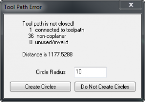
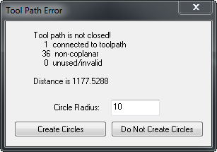
Click through the two dialog boxes which are part of the SCToolpath command
Important: If you get an error box select “Do Not Create Circles” and cancel the command by pressing ESC. Continue the part creation by running the command SCCreatePlatePartFromSolidCont
Select the pick point (inner point) of your plate part
Select the part properties (stock, throw/mark direction, etc.)
Repeat
SCCreatePlatePartFromSolidCont
Select 3 points on the outer toolpath
Select all the geometry using AutoCAD selection box
Select the pick point (inner point) of your plate part
Select the part properties (stock, throw/mark direction, etc.)
SCCreatePlatePartFromSolidWithHoles
Very similar to SCCreatePlatePartFromSolid. I bolded the unique step.
Select or preselect the part you want to convert
The command will Isolate the part (hide all other parts), zoom to the part and move it to the PartCreated Layer
Select the part again
It will explode the part.
Note: In some cases I was able to remove this step but it did not work consistently so we are forced to have this step
Select the plane of the explode part which you want to be the mold/construction plane
The command will Isolate the plane you selected
Select the plane again
The command will convert the plane into its geometry which we will use it to generate the part
Note: In some cases I was able to remove this step but it did not work consistently so we are forced to have this step
Select 3 points on the outer toolpath
Select all the geometry by using the selection box window. It is important to select all the geometry on the first try. This is a nuance of CUI scripting.
Select the pick point (inner point) of your plate part
Select the part properties (stock, throw/mark direction, etc.)
Repeat
Video
If you do not have access to YouTube you can view the video here.
Denis has been internationally recognized for his published blogs, articles and papers and continues to provide insights on innovative solutions for the marine industries. He has worked hand in hand with industry partners and SSI’s clients around the world to solve their most difficult business and technology challenges. This depth of understanding of both the current and future state of technology and the business of shipbuilding serve Denis well as he leads SSI towards the delivery of innovative products and services.